Technical Tips + Advice
Technical Tips, Advice & FAQ's
There are several ways to get Technical Info on these great motorcycles. Below we offer few popular tips. You can also purchase a Mustang Operation Manual from Eric Wentzel, purchase copies of Mustang News Magazines, and be sure to check out tour FAQ's.
There are several ways to get Technical Info on these great motorcycles. Below we offer few popular tips. You can also purchase a Mustang Operation Manual from Eric Wentzel, purchase copies of Mustang News Magazines, and be sure to check out tour FAQ's.
|
Headlight Gasket Tip
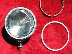
I was working on son's Dave Bronco today and noticed the chrome headlight was showing signs of rust..I removed it and disassembled it and it was badly rusted through out the entire inside..I removed all the rust as best I could, I soldered new wires, cleaned the lens and polished the silver reflector..It was looking a lot better and when I started to reassemble the lamp, I noticed that the cork lens gasket was not in good shape and realized that it was partly responsible for contributing to the rust factor..I sure was not going to compound this felony by using the same material..What I came up with is using a semi-ridged plastic tubing with an outside diameter of 1/4" and a inside diameter of .170"..I'm sure I picked this up at the local hardware store. The developed length is 18 3/4" long..I used a 'Q" tip to connect the ends..I cut the "Q" tip in half, stuck the cotton end in the tubing and joined the other end to form the circle..Now, it's all plastic, will not absorb moisture and will not rust!. The attached photo shows both a new plastic gasket installed and one shown along with the old original cork gasket....Works for me! -FWIW, Jimbo. |
|
Speedometer Repair
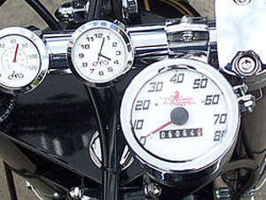
My speedometer worked just fine but it was "dingy" looking compared to the rest of my bike after restoration. I located the Joel Levine Company in Atlanta ,Ga. and arranged to have the unit rebuilt and a new dial with new artwork included. He was able use the silk screen process to recreate the art and the other graphics. NICE! The workmanship was excellent but pricey! I elected to keep the original mileage on the odometer but he did offer to reset it to zero miles. The smaller clock and ambient temperature gages shown are after market and available. Joel Levine Company — (800) 456-6267 |
|
Tank Strap Retaining Spring Idea
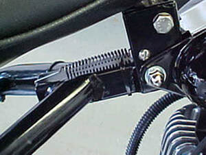
FWIW, here's a neat method of retaining the gas tank center strip. No bending, rolling or swearing! It conforms to the contour of the fuel tanks and is so easy to install. First, if the tab on the center strip is bent or wrinkled, straighten and then drill or punch a small hole about midway in it's length. Then locate a suitable spring and connect the spring in the drilled hole and the other end in the end of the frame tube...Then install a No. 10 machine screw & nut across the seat bracket in the existing hole (where the cotter pin used to go)..this will hold the tab down and will fo the contour of the tanks. What's nice about this is that you can reuse the strip over & over. — Jimbo |
|
Crankshafts: Interference Fit
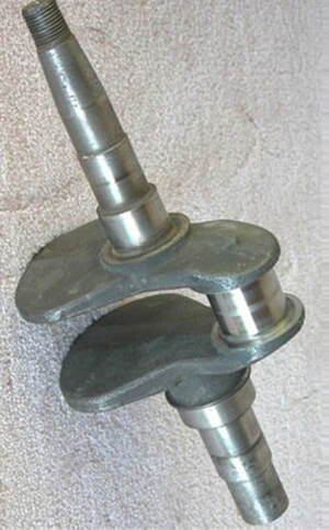
Mustang crankshafts with the integral timing gear, were usually one piece design. This photo is of a Model 2 crankshaft. But the following info is typical of all the model crankshafts, made by Gladden Products Corporation. Look again and you will notice that there is no timing gear! Why, what happened? Well, in the production of this key component, machining errors would require certain reworking. I've mentioned before how we salvaged undersize cranks by metal spraying. But, too often, a integral timing gear defect would render the crank unusable. Sometimes if a crank was dropped and landed on the finished timing gear or if the timing gear blank did not clean-up to allow for a successful gear cutting, it was unusable. In these cases, we would accumulate these conditions and turn off the complete gear blank and grind, on centers, to a finished diameter for a replacement gear blank. We had finished gear blanks, (not available as a spare part) which we would heat to about 500 degrees and drop it on the turned diameter. This method is called Interference Fit. They would be locked on forever and no one could tell the timing gear was added after the fact. Because no fixture was used to "time" the gear tooth to the crank pin, some engines would have advanced timing or retarded gear timing as much as one tooth. This is one reason one bike would run better than the norm or have a little less horsepower. — FWIW, Jimbo |
|
Chronic 3-Speed Tranny Weakness
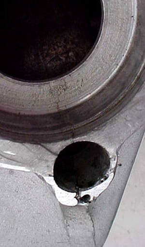
The Burman three speed transmission, over the years has proved to be rugged unit, even though it has its limits. This unit was first introduced in the Mustang line in 1948 as original equipment on the Model 2. Soon thereafter, it was used on the Model 3, the first Deliverycycle, then about 1950 the Model 4 and Model 5 Deliverycycle. I believe that the extra load of the three wheelers first proved that a chronic weakness existed in this otherwise, small compact transmission. If you look closely at the photo of the M-1615 Shell, you will see a crack that runs completely thru the lay shaft bushing bore, and continues up and into the main drive bearing bore. This serious failure renders the transmission unusable. Early on, it was brought to the attention of the Burman people and they subsequently made a foundry tooling change to “beef up” the casting adding more material to the weak areas. This change was enough to correct the problems with the trikes but still was a common problem with the solo units. This key component of the unit is now precious, thus the reason for this writing. To prolong its useful life and avoid having your 3-speed tranny fail, DO NOT: 1.) Do “Burn Outs” 2.) (Speed) shift without using the clutch 3.) Don’t do “Wheelies” 4.) Also, keep both the primary chain and the final drive chain adjusted properly and in good condition. A rough spot on either chain causes shock when it passes over the sprockets. FWIW! — Jimbo |
|
Jimbo's Quickie Work Stand
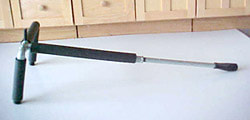
A quick way to repair, service or show your Mustang. Simply slide under your Mustang and lift. Stand is similar to the one that I used while building Mustangs for almost 20 years as Mustang Production Manager! You may e-mail me at jimbocav@oip.net I will be glad to answer any questions. — Good Luck! - Jimbo MATERIAL: 1/2 inch, schedule 40 (NPT) galvanized water pipe.. 1 pc 1/2" NPT pipe “T”…. 1 pc 1/2 “ NPT x 12 “ long, pipe nipple (this will be the spreader bar between the two uprights) 2 pcs. 1/2” NPT X 7” long, pipe nipple (this will be the two uprights) 1 pc 1/2” NPT X 34” long, pipe nipple (this will be the handle) 2 pcs. 1/2" NPT Street elbow, Attach the 34” handle to the middle leg of the 1/2” “T”…Attach the 12” Spreader bar so it’s horizontal to the other leg of the “T”…Attach the 1/2” Street elbow to the “T” and attach one 7” upright…Next, attach a 1/2” Street elbow to the end of the Spreader bar and the 7” upright… At this point you have the basic stand together…You should drill a 3/8’ through the Spreader bar right in front where it connects to the “T” …Place a 3/8” Head Cap Screw X 3” long (approx) retained by a hex nut…This will become a ‘Peg” that you would place along side a motor mount so that when the bike is on the stand, it will not slide off while you have it up off the floor…I recommend putting rubber cane tips on the ends of the uprights… A bicycle handlebar grip could be installed on the end of the handle…Also, to protect your beautiful paint, pipe insulation wrap is available to cover all the pipe…Also, a piece of 3/8” hose can be put on the peg to protect your finish… Note: the handle can be made using two 17” nipples and joined with a 1/2” pipe union so that the stand can take up less space. .This would make it ideal for portable use. Submitted by Jim Cavanaugh |
|
Mustang Workmate
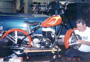
I recently assisted my son David in assembling his Mustang Bronco from scratch. I wanted a comfortable workplace with the correct height and be able to walk completely around the unit while it was under construction. I had it firmly fastened to something solid much the same way as we did in the Mustang factory some 40 years ago! What I came up with, was the Black & Decker workmate 300 portable work station and two (sometimes three) Quick-Grip bar clamps with padded grips, made by Vise-Grip (American Tool Co.) The B&D workbench top opens enough to clamp-up the oil pan. The bar clamps can be used to clamp the frame in many places without scratching the paint or powder coating. This is so close to the factory method of holding the Mustang it's uncanny! This could also be a good way to display the finished bike, besides having a very useable item in the workshop. The above items are available at most tool departments at Home Improvement supply houses or the larger hardware stores. |
|
Mustang Model 2 Lighting
I wanted to be able to ride my Model 2 during day light hours, and I do not have a generator. Solution was to hide a small battery to run brake light only. I wanted to hide the battery as best I could, so I used a small Gel Cell from a 1999 Repro Whizzer. First I found a location under the right hand side, and below the transmission I made a heavy paper pattern around the battery, then used that as a template to cut sheet metal. It was folded to form the battery box (note 2 mounting ears). The flat trans. mounting plate was drilled and tapped to accommodate the two screws. I also used 2 small pieces of double sided tape the back of the battery to help support it. I used a LED tail/brake light which is said to draw 1/10 the current of the standard bulb. Submitted by Warren Burdine |
|
Weak Spark
The magnetic charge in the rotor weakens over time. Try a test by taking an old spark plug and adjust the gap to say .050 or twice the normal gap. Place it on the engine block somewhere so the threaded shell is grounded. With the spark plug lead attached, crank the engine over like you were trying to start it. You should notice a nice blue spark jump the gap. If the spark is orange color or whitish, or no spark at all, the voltage is low and the rotor should be recharged. Alan Wenzel will recharge a rotor for a nominal charge. Submitted by MMCOA. |
|
Starting Up a Mustang that has Been Sitting for Sometime
Remove the spark plug and crank the engine over a few times to avoid a hydraulic lock up. Oil technology has improved, but I recommend a high quality SAE # 30 wt motor oil such as Valvoline. I would remove the gas cap and attempt to smell the fuel tank for signs of varnish. Gasoline turns to varnish quickly after sitting for just a couple weeks. It would have a distinct odor just like varnish. Rust in the tanks(s) is always a concern after sitting. If there is varnish deposits in the fuel tanks, chances are it's in the carburetor. The only way to rid this varnish in the carb is to disassemble and clean all the parts and passages with a carb cleaner. Look for the same signs in the fuel lines and sediment bowl or on-off valve. |
|
Air Filters!
Don't forget that air filter on your Mustang engine. Two reasons not to forget. First, when the engine ingests dirty air, excessive wear of the intake valve guide and piston/cylinder occurs prematurely. Second, when the bike is under way, a "ram air" effect occurs without the filter in place and the air/fuel mixture (ratio) is disturbed making a lean condition. It could be argued that the Model 2 did not have an air filter. Which is true and I don't know why this happened, but there is no ram air effect because the carburetor is behind the engine. Submitted by MMCOA. |
Crankshaft and Flywheel Insurance
Make sure you have a grade 8 cap screw and that it easily threads into the crankshaft all the way by hand. The plain washer should be thick, like 3/16". The factory used an internal tooth lock washer which are available. Locktite was never used, but it would not hurt to put a drop on it. What I do, is lap the flywheel to the crankshaft taper with very fine lapping compound and clean it off good. Then use an aluminum key in lieu of the steel key. This way, should the engine suddenly stop or work loose, the flywheel and crankshaft will survive without injury. Torque is not mentioned in the manual, but I would really torque it up good, maybe 350-400 inch lbs. The big problem is holding the flywheel from turning while you tighten it. At the factory we had several tools to do this. One was a piston stop and the other was a lever which used the three holes in the flywheel. The 3/16" aluminum key stock is available at Ace Hardware or other quality hardware outlets. The fine lapping compound is available at auto parts stores.
Submitted by MMCOA.
Muffler Replacement
If you have a new exhaust muffler and need to attach a hanger to the muffler, brazing is NOT recommended. If you can Heli-arc or Mig weld, it would be a lot better and produce less heat. I remember at the factory, after chrome plating, we welded a cad plated bracket about an inch wide by about 2-1/2" long and 1/8" thick. It was located in the middle of the muffler. We touched up the weld with silver paint which never showed. If the exhaust pipe was down swept, it was just bolted to the lower chain adjuster bolt on the right side. If it was an upswept pipe, it was bolted to the vertical (rear) fender brace which had to be drilled for the 1/4" bolt. It also had to be bent a little to offset (by rolling) the bracket. On the assembly line, drilling the vertical brace for the muffler bracket, too often the assembler would neglect to place a piece of wood behind the fender brace and drill right into the rear tire. Unmistakable POP! If they did it twice, they were history.
Submitted by MMCOA.
Lubricating Front Forks
If there is a lot of oil seepage at the front forks. It is recommended that you use grease instead of oil to lube the front forks. There are many hi-tech lubricants available at your local auto supply.
Submitted by MMCOA.
The upper telescopic fork aluminum bushings can be grooved for an Indian distributor felt part number 50183. With this felt installed it will have lubrication for a much longer period of time and yield better fork action and less bushing wear.
Submitted by Ted Williams, #804, Wheatland, CA.
Fork Assembly Tips
Over the years, I have filled a drawer with chains, cables, eyebolts, straps and turnbuckles, for every new idea I had on an easy way to do it. One day, it hit me, I had the tool all along. Most people do, and if you don't, it doesn't cost very much. All you need is a hose clamp, put hose clamp around lower tube. Stand assembly up on piston end and compress the spring by pushing down on bushing. Tighten clamp while this is compressed and the bushing will be held in place. You might want to use a piece of tape under the clamp, but I've never scratched a tube without it. Now lubricate the bushing and slide the assembly in the upper fork tube. You only have to compress the upper spring about an inch to bolt the bushing in the fork. While holding down on lower tube, release the clamp and slowly let the lower tube up in the fork.
This method gets the job done. Hope this helps to relieve some of the stress related to Mustang restoration. And to all those who have assembled forks in the last few months.
Submitted by Alan Wentzel
Replacing the K/S spindle on a Burman 4 Speed Transmission
If you have not removed the outer cover, put the gear selector in neutral. TIP. Remember to hold onto the K/S lever or it will spin violently when you remove it. The K/S spindle is a slip fit into the main case and will pull out easily.The gear segment and return spring will come out with it. Remove the spring and the gear segment and re-install on the new spindle. Slip the spindle assembly into the cover and be sure to place the spring end eye on the pin anchor. Temporarily, slip the K/S lever on the splined spindle and wind the K/S lever counter-clockwise to wind or pre-load the return spring. Wind it all the way and then back it off at least one full turn. The outer cover assembly should slip back onto the case with out any interference. You will have to be sure the K/S gear segment nests on the return stop.
Mustang Timing
I use the factory method to set the ignition timing which requires the cylinder head removed. A special timing bar that is easy to make if you have basic machine tools. It involves a piece of steel bar about 3/8" thick and about 1-1/2: wide and drilled in two places to pick-up two opposite head bolt holes in the block. Then a piece of steel carefully made to exactly .250 (1/4") thick some how fastened to the middle. This becomes a piston stop to insure that the piston is exactly 1/4" before top dead center (BTDC) for timing. Place a continuity meter or low voltage light to the ignition points and the other lead to ground. Set the ignition points to .018-.020 gap. By rotating the mag stater plate one way or the other, the meter or light should make contact and make & brake. Set it as sensitive as you can, making sure that when you tighten the stator retaining bolts, the timing doesn't change. It usually does change and you have to fine tune the adjustment by sneaking up on the tightness or alternating the tightness from one bolt to the other. The piston stop timing bar also is a good way to keep the engine from rotating when tightening the flywheel or engine drive sprocket. If you don't want to go to the trouble of making the timing bar, you must somehow assure that the piston is exactly .250 ( 1/4") BTDC perhaps using a dial indicator or other clever way to set this piston position. Once the piston location is set, I always make a land mark(s) on the flywheel face and the bearing support plate using a scribe . This way, you know where the piston position is without removing the cylinder head. I also make landmarks on the stator and the bearing support plate after the engine is timed, so that the ignition timing can be set approximate should the mag be removed for any reason. But this procedure will only give approximate correct setting. True setting must be done using the confirmed piston position with the timing bar or dial indicator method. It really is worth your time to make the timing bar.
Submitted by MMCOA
Cam Axle Repair
Recently I was sitting at a stop sign and much to my horror, I noticed my cam axle was sticking out on the left side about half an inch and was turning. After knocking it back in with a rock, I made a bee line for the house. I made several calls to different Mustang folks and was offered a number of suggestions, including WELDING IT IN! Here is what worked for me. I removed the engine from the base, pulled the flywheel and mag and pushed the axle out. Then I drilled a #7 hole through the front of the block and through the cam axle boss on the inside of the engine. Drill it as close to the center line of the axle boss as possible. I then tapped the hole 1/4-20. With a die grinder, I ground a flat on the axle to line up with the previously tapped hole in the block. I reinstalled the axle and locked it in place with a 1/4-20X1 1/2 inch set screw. For additional security, I used a lock washer and a cam nut on the protruding portion of the set screw (Note: a chrome acorn nut looks really neat-o and is good for 2 hp). Be sure to clean the inside of the engine thoroughly before reassembly. I hope this helps somebody with the same problem.
Submitted by John Callin
Replacing Cam Axle
Many owners want to replace an old cam with the new full race cam to give their bike more power. There is a right and wrong way to do this. If the cam axle is removed improperly, it could severely damage the cam axle support holes in the block. The most common way the axle was removed by rebuilders was to drive the axle out with a hammer and brass drift punch, steel punch, bolt, or whatever was handy. The only problem with this method is that it tends to swell the end of the cam axle. As you drive it out, the holes in the block are damaged to the point of causing a loose fit for oil leakage when the cam axle is installed. One of the best methods of removing the cam axle is to have it pressed out with a hydraulic or arbor press at your local machine shop. You should be able to have this done very reasonable at your local machine shop. It should also be pressed back in the same manner. Note: The cam should be pressed out towards the drive side of the block and back in from the flywheel side. Oiling the holes will be of great help as will FREEZING the axle before installation. The little extra trouble it takes to go to the machine shop may save you allot of trouble down the road.
Submitted by Larrry Zorn
Powder Coating
Recently, I have been restoring another Stallion with a lot of personal use in mind. This is to be the rider I have always wanted with use more important than show! I have become rather intensely involved with Turbo-Mach II a local company which does powder coating here in the San Antonio, Texas area. First thought was to powder coat the frame as many do when starting a restoration project. At the suggestion of my friends at Turbo-Mach, we clear coated over the black coating and the results were outstanding! The next thing to happen, was when attempting to polish the primary covers, the more I polished, the more large pits I could see! Well, I really didn't want polished covers anyway (you bet). So, what the heck, We'll use sand blast finish as were the originals. Surprise!! More pits, only larger! Well, no problem, we will Heliarc the pits, grind then off and sandblast. Yea, you bet, a bigger mess yet, and even more pits! Matter of fact it got to the point that I was convinced that a hard look or stare could provoke more cavities! So, we powder coated the primary after filling the many pits with J-B Weld (which incidentally is the filler of choice when powder coating at 400 degrees because all else fails). Looked good except didn't match anything else. Not a problem, we just coated everything else, like the inner primary, lower crankcase and transmission case. I've always wanted a yellow Mustang, and I found myself looking for suitable powders to finish the tank and fenders. There it was, the perfect yellow, so we coated a rear fender to see what it might look like. After clear coating it looked like production enamel paint! Except there is a tiny dent we didn't see. This stuff is supposed to be so tough, I'll just tap out the dent before I strip it for another go. Knocked the dent right out, except no harm came to the fender and you couldn't even see where I hit it numerous times with the hammer! This success only spurred us on to further folly! Since you can't do hardly any bodywork or primer surfacing, we just ordered up a set of new tanks. Found that to be a big mistake, the new tanks were terrible! Waves and dents were everywhere! The original tanks were looking better all the time. Taught myself the rare technique of pushing out the dents from the inside and filled the very shallow dents left with J-B Weld. We heat cycled the part and found an earlier repair done in the old days using body solder. It melted out and fell to the oven floor. We were getting better at paintless dent repair anyway, so we did it over again, hear cycled the tanks again and everything looked good. Powder coated yellow and clear and they looked pretty good if you like oranges. We knocked out the minor dents in the front fender and finished it also. Laid awake nights when I discovered that I hate orange peel! Tried to imagine the easy way out. Try and wet sand out the orange peel or remove this near unremovable mess or call it primer! It was easy enough to wet sand with 1000 grit, if you don't mind endless sanding, like sanding glass. Went out and bought a finish sander! Boy this dude works! You get the idea that you just might live long enough to finish. With the usual false starts, we settled on sanding out the surface to smooth using 1000 grit wet and following with Micro-Kut and foam buffer, then changing to Liquid ebony to remove swirl marks and to polish. The results are worth the effort. Dropped the fender! Well, pick it up, no damage, keep polishing! Powder coating is the most durable and tough finish one can imagine. Polyurethane plastic is fused and cross linked to the metal surface at 400F degrees. The big problems are that anything coated must be near perfect as there are few known fillers and no primer surfaces. Sanding may be used to smooth the finish, but the stuff sands like concrete! This near fatal flaw, high heat requirements and the fact that powder coating on flat surfaces orange peels like crazy has stopped universal use of the process. BMW is/has been trying to powder coat an entire car for sometime now and we can imagine how much fun they are having. We polished the wheel hubs, brake backing plates, and transmission case and clear powder coated with very good results. Never have to polish them again. Good, cause it only took nine hours and are near impossible to do again after the wheels are laced. Because of the heat, decals must be left on the surface as were the originals and strip-ins will have to be laid on by hand as were the originals. Just noticed that the Mikuni and cylinder head need powder coating! What the heck, no one is perfect! Someday, after we are long gone, there might be another restoration on this bike and there's gonna be someone cussin' me! Till then I'll have the toughest bike around!
Submitted by Fred Hoese
Valve Stem Wheel Hole Adaptors
While installing new tubes on my old rims I find the hole in the rim for the valve stem is much larger than the diameter of the valve stem on the tube. This problem can allow water and dirt to get inside the rim and tire. I have not been able to find any of the old style tubes, with the fat valve stems. I was talking to a fellow Mustang enthusiast Paul Geary, and he told me of a plastic adapter that fits over the valve stem and then plugs into the larger hole in the rim thus centering the valve system and keeping dirt out. This adapter will give a finishing touch to your dise or wire restoration. These adapters are a little hard to find in my area, as they don't use them much anymore. I ordered a box of them from my tire dealer so I would have them in stock for anyone who needs them.
Submitted by Larrry Zorn
Solid Rim Repair/Recovery
Solid Rim Recovery A while back I saw serious failure in rear wheel of my 53 Pony. Peeling paint and then actual crackes and breakes around bead area then the tire went flat. The rear wheel collapsed from corrsion. The flare area on both sides of wheel was very thin, almost like you could punch your finger right through it. I bought another rear wheel from west coast but wheel is not true and not round. It's usable but far from perfect.
I took my junk wheel to my friend, a master welder, here in this agricultural community. He took some time to study the problem. After much thought he said that he could repair my rear wheel. He found a similar 12" wheel at an implement store. He torched of flares on my junk wheel, and then torched the flares off the new wheel. He then welded the flares from new wheel to my junk pony wheel. This guy is a craftsman. Pony wheel is staight and true. Rim on repaired wheel stamped "Made in USA 2004"!
Wheel is sold as a replacement for trailer wheels. Made in USA. We found it at A-A Wheel, but you could possibly find it at The Family Center, or Tractor Supply.
Part Number: 12440WS
Cost: $26.4
A-A Wheel 717 E 16th Ave.
North Kansas City, MO 64116
Tel: 816 221 9556
Submitted by Stephen Spruill
